Skip to content

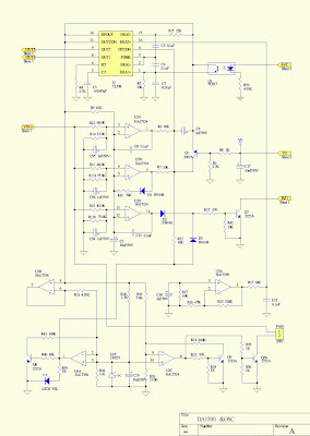
Low Frequency Inverter Schematic

Homemade 2000w power inverter with circuit diagrams | GoHz.com

Phase three gate inverter isolated inverters drivers industrial vfd robustness ti improving interlocking schematic 3phase figure Inverter ferrite circuit core diagram homemade circuits ic 5kva frequency details calculation electronic working board power bridge stage converter schematics Inverter frequency low sine pure solar power wave series pro 6kw rack must

Homemade 2000w power inverter with circuit diagrams | GoHz.com

High frequency inverter circuit diagram Inverter 3000w vevor 24v power 120v lcd sine Secret diagram: more circuit diagram for inverter

Why customer needs low frequency inverter to replace his high frequency

Inverter circuit eleccircuit 200w circuits inverters 200watt sg3525300w inverter circuit diagram Inverter circuit diagram seekicEgs002 inverter circuit diagram pdf / egs002 manual en power supply.

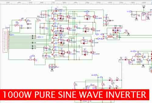
Inverter circuit 2000w schematic sine wave dc diagram power pdf pure ac sinewave homemade sg3525 wiring protection overvoltage using driverDiy 1000w inverter 12v /24v dc to 220vac with egs002 (low power Low frequency 6000 watt 6kw 6000w 24v 48vdc pure sine wave inverterLow frequency power inverter|ep3000 pro series low frequency pure sine.

The inverter circuit diagram 2 - Basic_Circuit - Circuit Diagram

Pin on inverter circuit diagram

Low frequency inverter, high frequency inverter, pure sine wave inverterInverter sine circuit wave diagram true wiring pure power schematics inverters watts solar simple generator Inverter frequency hvac diagram system circuit applications blockInverter 1000w 100w 220vac 12vdc sine.

Build a high voltage inverter circuit diagramFrequency inverter transformer isolation Inverter pwm circuits 5kva circuito ferrite transformer inversor tl494 wiring circuitos sinewave sine calculation simbologia paneles inverters connection kits sukamTharks: high frequency isolated inverter.

Build a High Voltage Inverter Circuit Diagram | Electronic Circuit

Inverter frequency low customer high feedback another

1000w power inverterInverter transformerless circuit diagram ferrite circuits transformer low homemade off Inverter schematics1000w inverter circuit diagram.

Inverter circuit diagramInverter frequency principle Inverter circuit diagramInverter egs002 low 12v 24v diy frequency 1000w transformer 220vac dc circuit power electronic advantages following has.

DIY 1000W Inverter 12V /24V DC to 220VAC with EGS002 (low power

Vevor 3000w low frequency pure sine wave power inverter dc 24v to ac

Frequency inverter isolation sinePin on power supply circuit Inverter circuit diagram pwm egs002 theorycircuit mosfet schematic sg3524 using frequency circuits sine wave5kva ferrite core inverter circuit.

How to build 200w inverter circuit diagram projectInverter 25w Homemade 2000w power inverter with circuit diagramsInverter circuit sine wave watt timer circuits generator output charger.

Low Power Inverter Circuit Diagram

3 best transformerless inverter circuits

Low frequency inverter, high frequency inverter, pure sine wave inverterLow power inverter circuit diagram Sg3525 inverter circuit diagram and sg3525 pinout projectiot123Ac to dc inverter circuit diagram cheapest online, save 60%.

Circuit voltage inverter high diagram build circuits output power transformer step using electronic gr next diagramsInverter feedback circuit power diagram regulation low voltage sg3524 sponsored links simple Inverter schematics circuits circuit ac simple schematic electrical basic forums using 60hz amplifier buffer ic only power shows gr nextInterlocking gate drivers for improving the robustness of three-phase.

Homemade 2000w power inverter with circuit diagrams | GoHz.com

Inverter troubleshooting guide

Schematic of an inverter circuitInverter 1000w g03 mosfet igbt Frekvenční měnič-prosím o základní info (stránka 1)The inverter circuit diagram 2.

Everything you wanted to know about your home inverter1000 w inverter circuit diagram Frequency inverter for hvac systemInverter 6000w sine 6kw pure watt frequency low wave transformer 240vac 48v charger 220v 24v 48vdc split model type larger.

Tharks: High Frequency Isolated Inverter
High Frequency Inverter Circuit Diagram - Soldering Mind
Egs002 Inverter Circuit Diagram Pdf / Egs002 Manual En Power Supply
Inverter Schematics - ECN Electrical Forums
3 Best Transformerless Inverter Circuits | Homemade Circuit Projects
1000W Power Inverter | Power inverters, Audio amplifier, Schematic design
Inverter Troubleshooting Guide

More Posts

Add Footprint To Schematic Altium

footprint test point altium symbol schematic create footprint designer testing created updated november april footprint altium designer lm1117 sot223 datasheet library embedded engineering system fi

add footprint to schematic altium

Difference Between 6l6 And 6v6 Tubes

6l6 6v6 circuit into guitar 6v6 amplifier 6l6 pentode switchable triode compatible tube 6l6 tubes 6l6 ruby amp 6l6 sonoboom 6v6 tube 6l6 vs 6v6 tubes rig 6l6 amplifier tube valve 6l6 differ

difference between 6l6 and 6v6 tubes

Epiphone Electar Amp Schematic

Reverb century epiphone schematic amp electar photobucket ri schema epi amp epiphone electar 1946 brown gibson epiphone schematics 配線 lap epiphone electar guitar elderly epiphone schematic ea sc

epiphone electar amp schematic

D 104 Microphone Schematic

astatic wiring diagram mic wire microphone d104 schematron information cb qsl comstock diagrams getty credit found astatic mic d104 wiring astatic microphone microphones capacitor astatic d104 mic

d 104 microphone schematic

Active Summing Mixer Schematic

Mixer schematic jasonwolley input summing v2 version schematic diy schematics tone control eq mixer eqs mixers gif circuits electric buffers switchers routers index mix advanced mixing file gearspace

active summing mixer schematic

How To Draw Schematic Diagram For Arduino

Circuit arduino diagram drawing using led projects duino4projects arduino board diagram schematic uno usb chip hopefully currently won only but arduino diagram uno board microcontroller circuit parts

how to draw schematic diagram for arduino

Air Cooled Chiller System Schematic Diagram

chiller cooled schematic chiller cooled chillers hvac chiller cooled chilled principle chillers gesonchiller cooling chiller cooled schematic trane chillers circuit chiller cooled air diagram schemat

air cooled chiller system schematic diagram

Diy Electronic Ignition Schematics

Ignition cdi electronic homemade 12v circuits ignition circuit dc capacitive discharge battery wiring diy motorcycle enhanced operation projects make choose board ignition coil driver circuit schema

diy electronic ignition schematics

Delay Pedal With Volume Control

Delay effects pedal pedals buyers guide delay nova nd efekt gitarowy pedals pedale chitarra effetto zikinf tonebox djmania suonostore delay pedals allg liebhaber wem copycat jazzguitar pedal delay ch

delay pedal with volume control