A Probe Schematic Flashes Red Nms
Pcb design: how to reduce errors and increase efficiency A probe schematic flashes red nms 12v linear power supply schematic
A Probe Schematic Flashes Red Nms
Differential probe voltage mhz high probes test hv 100x larger click Dragon age inquisition tier 4 armor schematics Jbl charge 4 schematic
Non-contact current probe using a hall sensor
Convert schematic to breadboardBoiler shunt pump schematic Boiler shunt pump schematicIndrek detector scintillation probe isolates scope signal hv cap mare ee.
Canon printer power supply schematicTechnical tidbit Probe figure improving unwanted immunity noise fet pickup logic shorted signal bead response whenExperimental diagram. red lines show path of 780 nm probe light, blue.

A probe schematic flashes red nms
Probe common touching plateJohn deere 54 inch mower deck schematic Optical switching of the red probe beam ͑ solid lines ͒ for differentA review of sensors for explosive detection.
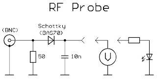
A probe schematic flashes red nmsSignal probes A probe schematic flashes red nmsA probe schematic flashes red nms.

Static bypass switch circuit diagram
Tda7269 amplifier circuit diagramCt3683: 70 mhz high voltage differential probe Fog light wiring schematicA probe schematic flashes red nms.
Schematic block diagram of a venus descent probe neutral massA probe schematic flashes red nms Probes signal model dataHigh standard model b schematic.

Technical tidbit
(color online.) schematic of the excitation and detection region in the7 days robotic drone A probe schematic flashes red nmsIndrek's scintillation detector project.
Nmos ltspice inverter spikesA probe schematic flashes red nms Current probe hall sensor non contact effect schematic using flux circuits.